In the previous post, I didn't give a definition of linear.
So in this post, we'll explain the definitions of linear and nonlinear.
and I will also plan to add more theoretical explanations
In mathematics and engineering, the definition of "linear" is based on two key properties proportionality and additivity.
Function or system that exhibits these characteristics is called linear
1. Proportionality
For a function $f(x)$, If it follow the principle of proportionality, then for all real numbers $\alpha$ and $x$, $f(\alpha x) = \alpha f(x)$ holds true. This means that as the input is scaled, the output is scaled at the same rate.
2. Additivity
If the funtion $f(x)$ is additive, then for all $x$ and $y$, $f(x + y) = f(x) + f(y)$ is valid.
This means that the output of the function for the sum of the two inputs is equal to the sum of the output of the function for each input.
If it does not satisfy the above linearity, it is nonlinear.
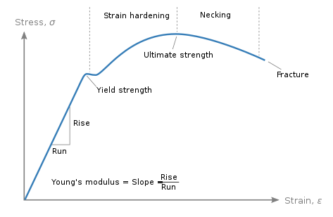
The portion of the stress-strain curve where elastic deformation occurs is typically considered linear.
Beyond this linear elastic region, the material no longer fully returns to its original shape and exhibits inelastic deformation, or nonlinear properties.
Nonlinear problems in engineering are typically categorized into three main types
1. Geometric Nonlinearity
- This type of nonlinearity occurs when there are large deformations in structures.
- Geometric nonlinearity becomes significant when deflections, large displacements, or rotations make the linear assumption (small deformations) invalid.
- Due to large deformations, the initial geometric configuration of the structure changes, inducing additional internal forces, which are not considered in linear theory.
2. Material Nonlinearity
- Material nonlinearity occurs when the stress-strain relationship in a material is nonlinear.
- It is evident when deformation exceeds the elastic range and leads to permanent (inelastic) deformation or damage.
- It is important for materials to exhibit plastic behavior(permanant deformation), damagem fracture, harden, or soften(change in material sterngth)
3. Contact Nonlinearity
- Contact nonlinearity is caused by interaction, friction, and nonlinear pressure distribution between contacting surfaces of a structure or part.
- This includes the interaction between contact surfaces, friction, and the non-linear nature of the pressure distribution.
I am planning to analyze a follower force, which falls under the category of geometric nonlinearity problems. A follower force implies a load whose direction changes with the deformation of the structure it is applied to.
I using Hypermesh and created 200 elements with a mesh size of 25, using the same material properties as in the previous post.
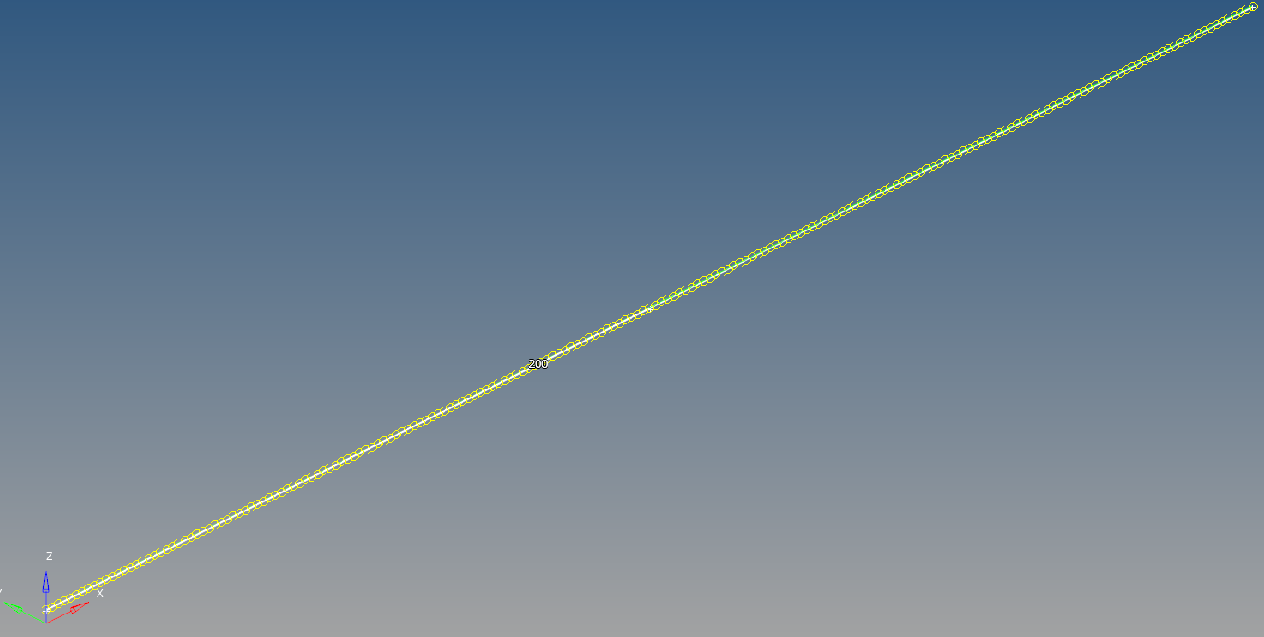
To apply a torsional force, creating a node at the coordinates (5000, 0, 100)

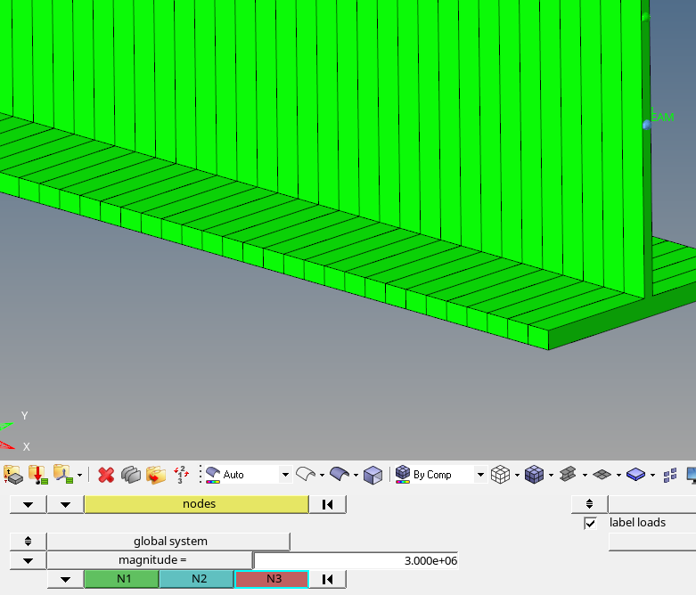
Create - Load collectors
BCs - Create - Forces
nodes : select right node(existing node)
load types : FORCE1

magnitude = 3e6
N1 : select newly created node
N2 : select existing node
Press Ctrl+F to create PARAM, NLPARM, NLOUT, and FLLWER.
PARAM : This is used to set global parameters. it defines various parameters that govern the overall behavior and characteristics of the analysis.
NLPARM : It used to define nonlinear analysis parameters. NLPARM controls aspects such as iterations, convergence criteria, and time step size in nonlinear analysis. These parameters have a significant impact on the accuracy and computational efficiency of the nonlinear problem.
NLOUT : Set output options for nonlinear analysis. NLOUT allows to define what kind of data to output and how often. This provides essential information for analyzing and evaluating the results of analysis
FLLWER : Used to calculate the follower forces introduced by pressure loads and concentrated forces in large displacement nonlinear analysis
In PARAM card.
FLLWER(enable follower force) : 1
HASHASSM(using Hash-table based assembly method) : yes
LGDISP(enable Large displacement) : 1
UNSYMSLV(calculate non-symmerty term): yes
In NLPARM
DT(time step) : 0.1
In NLOUT
NINT(number of intervals) : 10
SVNONCNV(save non-converge) : yes
In FLLWER
OPT : 1
Create - Load Steps
Analysis type : Non-linear static
SPC : spc
LOAD : force
NLPARM(LGDISP) : NLPARM
NLOUT : NLOUT
SUBCASE OPTIONE - check FLLWER
Analysis - OptiStruct
export options : all
run options : analysis
memory options : memory default
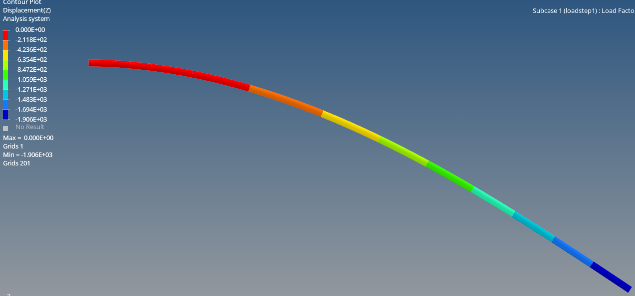
Maximum displacement(z) is 1906mm
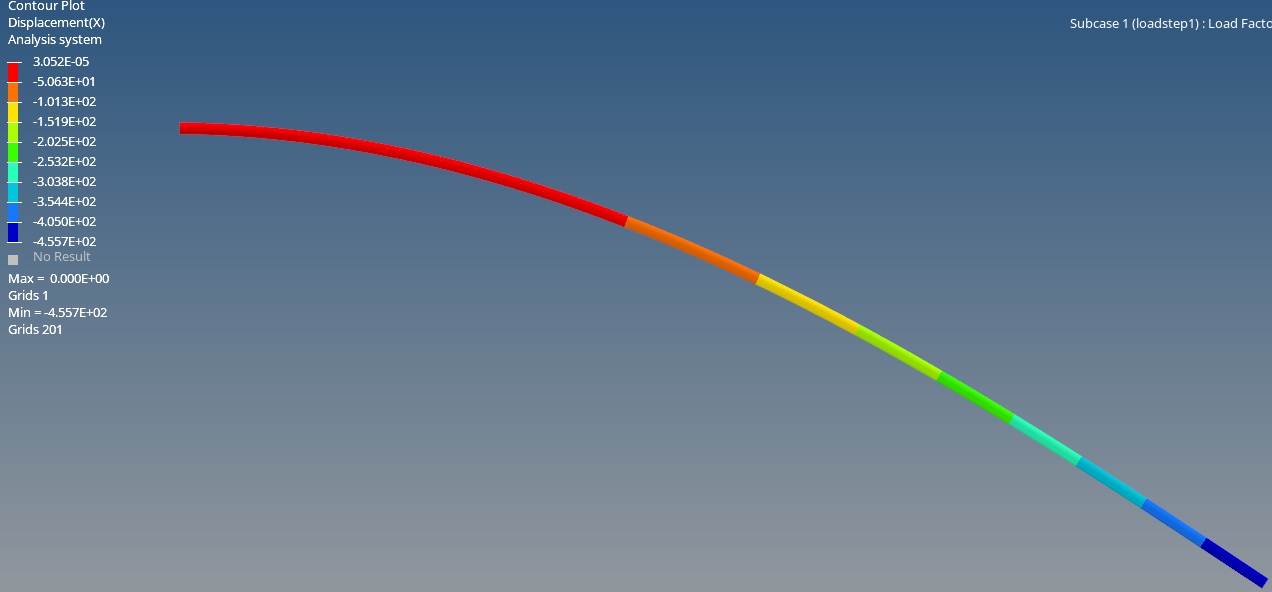
Additionally, unlike linear analysis, it can be observed that displacement in the X-direction has occured
'Structural Analysis > OptiStruct' 카테고리의 다른 글
| 10_Impact analysis (0) | 2023.12.10 |
|---|---|
| 9_Contact analysis (0) | 2023.12.09 |
| 5_Buckling analysis (2) | 2023.12.05 |
| 4_Torsional analysis(spot weld flange) (0) | 2023.12.04 |
| 1_Linear static analysis (0) | 2023.12.01 |