At the beginning of this blog, I calculated the teoretical Eigenfrequency and compared the theoretical solution with the analysis results obtained through modal analysis in COMSOL and Optistruct(7_Modal analysis and 8_Modal analysis(2)).
Today, I will conduct a Modal analysis with the same material properties and boundary conditions using Ansys.
The geometry to be used for the problem is as follows.

Geometric information and material property
$\eqalign{& {\text{L = 4550mm,I = 2700mm,E = 210GPa,v = 0}}{\text{.28,}} \cr
& {\text{density = 1}}{\text{.519}} \times {\text{1}}{{\text{0}}^{{\text{ - 5}}}}{\text{kg/m}}{{\text{m}}^{\text{3}}}{\text{,Cross}}\,{\text{section = 80mm}} \times {\text{130mm}} \cr} $
Calculating the Moment of inertia yields the following result.

The first natural frequency formula for beam is as following equation.

Run the workbench, drag and drop Modal into the Project Schematic.

To enter the material properties, double-click on Engineering Data and create a new material, setting it to Isotropic Elasticity. Also, add Density from Physical Properties and enter the material properties as follows.

The process of creating the Geometry is the same as in the previous posting(81_Cantilever Beam), with the only change being the Cross section to rectangle, hence it is omitted. The process of creating the Mesh is also identical and is therefore not detailed.
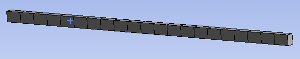
However, unlike in the previous posting, instead of fixing one end, pin and roller constraints need to be applied in the middle. Therefore, when creating the Geometry, it is necessary to connect three lines with length of 0.925m, 2.7m, and 0.925m, respectively.
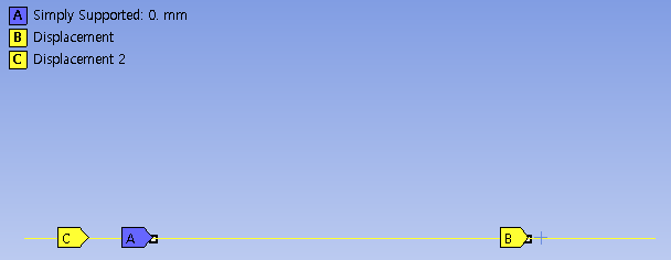
The constrains were set as follows: Part A was constrained as simply supported, part B had a constraint on vertical displacement, for example, if a line was drawn along the x-axis in the xy-plane, then the displacement in the y-direction was set to 0. Additionally, for part C, to ensure the line behaves only within the xy-plane, the displacement in the z-direction for the entirl line was set to 0.

When compare with the theoretical solution, there was about a 2% error. The left side of the above picture shows the results from Ansys, while the right side shows the results from COMSOL. It can be seen that they exhibit similar apperances.

The shapes according to the mode order are as shown in the above picture, and it can be observed that they exhibit identical shapes. Structural analysis through Ansys initially appeared to be somewhat complex, but as I practiced, it seems easy so far.
'Structural Analysis > Ansys' 카테고리의 다른 글
| 81_Cantilever Beam (0) | 2024.02.19 |
|---|